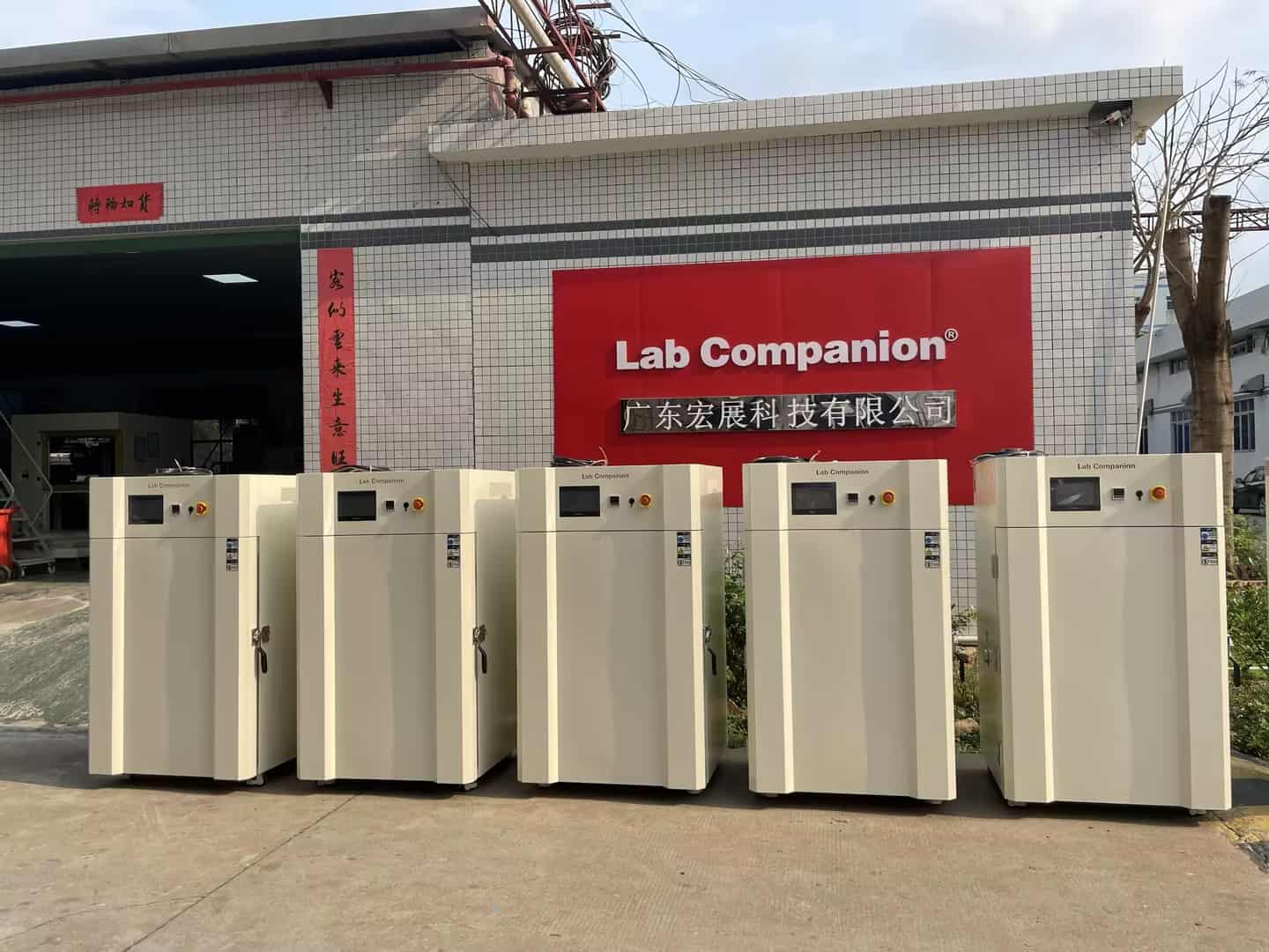
Proper maintenance is key to stable operation and long life of high and low temperature test chambers (manufactured by Lab Companion—Guangdong Hongzhan Technology with 20 years of expertise). Before cleaning/maintenance, remove internal impurities first.
1. Exterior Cleaning
Cabinet & Control Panel: Wipe with clean soft cloth; use neutral detergent for stubborn stains.
Notice: Avoid corrosive chemicals.
Power Cord & Plug: Inspect regularly for wear/cracks.
Notice: Replace damaged parts promptly to prevent electrical risks.
2. Internal & Accessory Maintenance
Filters: Check and replace regularly (based on usage) to block dust and avoid performance issues.
Water Tank & Pipes: Replace water and clean interior regularly.
Notice: Use purified/distilled water to prevent scale/bacteria.
Exhaust Fan: Inspect insulation and air duct blockages.
Notice: Clean every 6 months to ensure heat dissipation.
Temp & Humidity Sensors: Verify function periodically, and clean/replace if faulty to avoid test result errors.
Power Distribution Room: Vacuum dust annually to protect electrical components.
Power Distribution Box Panel: Wipe with dry cloth monthly; never use wet cloth to prevent short circuits.
3. Operating Environment
Placement: Install in dry, well-ventilated area.
Notice: Avoid direct sunlight, high temp/humidity.
Working Parameters: Operate within designed temp/humidity range.
Notice: Avoid overloading to prevent damage.
4. Performance Testing & Calibration
Performance Testing: Test regularly, compare with standard equipment for accuracy.
Calibration: Calibrate sensors/controllers periodically (at least annually, based on usage) for precision.
5. Record-Keeping & Operation
Establish maintenance records for troubleshooting.
Notice: Assign dedicated staff; follow guidelines to avoid unauthorized/improper use.
Follow these tips to maximize your chamber's performance and lifespan for reliable lab/industrial results.
For more advice or inquiries, contact Lab Companion—your trusted environmental test equipment partner.
1. Ежедневное обслуживаниеСначала очистите внутреннюю часть коробки, чтобы удалить все остаточные загрязнения (например, пыль и частицы образца), которые могли бы вызвать коррозию внутреннего слоя или загрязнение последующих образцов. После полного остывания коробки протрите внутреннюю поверхность, полки и внутренние стенки сухой мягкой тканью.Во-вторых, очистите внешнюю поверхность корпуса, чтобы пыль не засоряла вентиляционные отверстия и не мешала отводу тепла. Убедитесь, что вокруг вентиляционных отверстий нет скоплений пыли.В-третьих, проверьте, ровный ли уплотнитель дверцы коробки, нет ли на нём трещин и деформаций. Старение или повреждение уплотнительной ленты может привести к утечке тепла и снижению равномерности температуры.В-четвертых, опорожните камеру: опорожнение камеры после использования может предотвратить длительное хранение в коробке ненужных предметов, что может привести к загрязнению или несчастным случаям. 2.Регулярное техническое обслуживаниеПеред чисткой нагревательного элемента обязательно отключите электропитание! Дождитесь полного остывания прибора. Откройте заднюю крышку и аккуратно удалите пыль с поверхности электронагревательной трубки и воздуховода пылесосом или мягкой щёткой.Проверьте и очистите вентилятор/крыльчатку. Накопление пыли на вентиляторе может привести к нарушению динамического баланса, что серьёзно повлияет на равномерность распределения температуры. Поэтому после отключения питания необходимо проверить наличие постороннего шума в подшипниках двигателя вентилятора и с помощью пылесоса очистить лопасти вентилятора от накопившейся пыли. Электрические компоненты должны быть проверены профессиональными специалистами по оборудованию на предмет наличия ослабленных, обугленных или ржавых следов на линиях электропитания, автоматических выключателях, контакторах и других клеммных колодках. Затяните ослабленные клеммы и замените поврежденные детали, чтобы обеспечить безопасность и надежность электрического соединения.Точность датчика температуры может напрямую определять успешность или неуспешность испытания. Рекомендуется каждые шесть месяцев или раз в год проводить многоточечную сличительную калибровку рабочего диапазона температуры оборудования с использованием эталонного термометра, прошедшего метрологическую калибровку. При обнаружении отклонений следует скорректировать параметры системы управления или заменить датчик.Очистите систему увлажнения. Если ваше устройство оснащено функцией увлажнения, необходимо регулярно очищать поддон для воды, менять влажную ткань для предотвращения образования накипи и водорослей, а также использовать деионизированную или очищенную воду для уменьшения образования накипи. 3. Долгосрочное обслуживание после прекращения использованияСначала тщательно очистите внутреннюю и внешнюю часть коробки, а затем полностью накройте оборудование пылезащитным чехлом.Во-вторых, рекомендуется раз в месяц включать оборудование и давать ему поработать без нагрузки от получаса до часа. Это позволит удалить влагу из корпуса, сохранить электрические компоненты в рабочем состоянии, предотвратить их повреждение влагой и смазать механические части.Наконец, в периоды простоя рекомендуется полностью отключать основное электропитание, чтобы обеспечить безопасность и экономить электроэнергию в режиме ожидания. Всегда помните, что безопасность — превыше всего при выполнении вышеуказанных операций. Внедрение систематического плана технического обслуживания поможет продлить срок службы вашего оборудования. высокотемпературная печь, обеспечить точность и повторяемость данных испытаний, а также снизить частоту отказов оборудования и затраты на техническое обслуживание.
1. Литий-ионные аккумуляторы: Испытания при высоких и низких температурах проводятся на всех этапах НИОКР литий-ионных аккумуляторов — от материалов и ячеек до модулей.
2. Уровень материала: Оценка основных физических и химических свойств базовых материалов, таких как материалы положительных и отрицательных электродов, электролиты и сепараторы, при различных температурах. Например, проверка риска литирования анодных материалов при низких температурах или исследование скорости термической усадки (MSDS) сепараторов при высоких температурах.
3. Уровень элемента: Имитация зимних условий в холодном климате (например, от -40 ℃ до -20 ℃), тестирование запуска при низких температурах, разрядной ёмкости и скорости тока аккумулятора, а также предоставление данных для улучшения его характеристик при низких температурах. Циклические испытания заряда и разряда проводятся при высоких температурах (например, 45 ℃ и 60 ℃) для ускорения процесса старения и прогнозирования срока службы и скорости сохранения ёмкости аккумулятора.
4. Топливные элементы: К топливным элементам с протонообменной мембраной (PEMFC) предъявляются чрезвычайно строгие требования к управлению водой и теплом. Возможность холодного запуска является ключевым техническим препятствием для коммерциализации топливных элементов. Испытательная камера имитирует условия ниже точки замерзания (например, -30 °C) для проверки возможности успешного запуска системы после замерзания и изучения механического повреждения каталитического слоя и протонообменной мембраны кристаллами льда.
5. Фотоэлектрические материалы: Солнечные панели должны служить на открытом воздухе более 25 лет, выдерживая суровые испытания днем и ночью, а также все четыре сезона. Моделируя перепад температур днем и ночью (например, 200 циклов от -40 ℃ до 85 ℃), можно проверить термическую усталость соединительной ленты аккумуляторных элементов, старение и пожелтение инкапсуляционных материалов (EVA/POE), а также надежность соединения различных ламинированных материалов, чтобы предотвратить расслоение и разрушение.
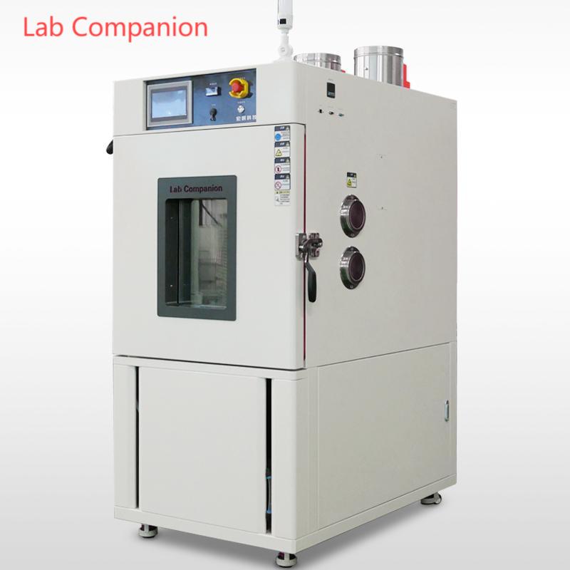
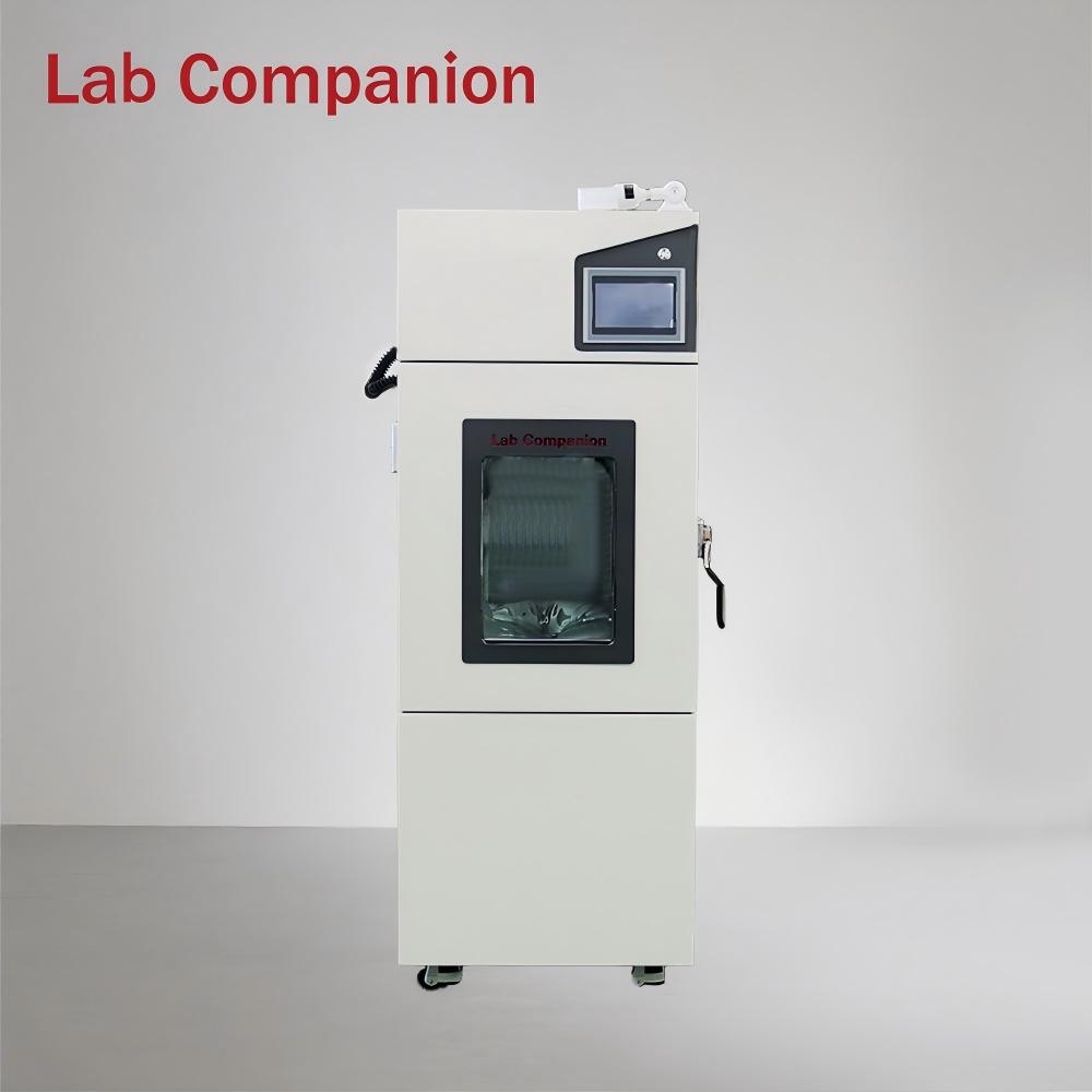
Современные испытательные камеры для высоких и низких температур Это уже не просто камеры для измерения температуры, а интеллектуальные испытательные платформы, объединяющие множество функций. Усовершенствованная испытательная камера оснащена смотровыми окнами и тестовыми отверстиями, что позволяет исследователям наблюдать за образцами в режиме реального времени при изменении температуры.
Выбор места установки испытательной камеры быстрого изменения температуры:
Расстояние от соседней стены позволяет в полной мере реализовать функции и характеристики испытательной камеры для испытаний на воздействие окружающей среды. Следует выбрать место с длительной температурой 15 ~ 45 °C и относительной влажностью воздуха более 86%.
Рабочая температура в месте установки не должна существенно изменяться.
Его следует устанавливать на выравнивающей поверхности (используйте уровень для определения уровня на дороге во время установки).
Его следует устанавливать в месте, защищенном от воздействия солнечных лучей.
Его следует устанавливать в месте с хорошей естественной вентиляцией.
Его следует устанавливать в местах, где отсутствуют легковоспламеняющиеся материалы, взрывоопасные продукты и источники тепла высокой температуры.
Его следует устанавливать в месте с меньшим содержанием пыли.
Устанавливайте его как можно ближе к импульсному источнику питания системы электропитания.
Камера для испытаний на высокие и низкие температуры могут возникнуть различные проблемы в процессе использования, ниже приведен краткий обзор потенциальных неисправностей и их причин с разных точек зрения:1. Сбой основной системыТемпература вышла из-под контроляПричина: Разбалансировка параметров ПИД-регулятора, температура окружающей среды превышает расчетный диапазон оборудования, многозонные температурные помехи.Случай: В цехе со специальными условиями эксплуатации высокая внешняя температура приводит к перегрузке холодильной системы, что приводит к температурному дрейфу.Влажность ненормальнаяПричина: плохое качество воды для увлажнения приводит к образованию накипи и засорению форсунок, выходу из строя пьезоэлектрического листа ультразвукового увлажнителя и неполной регенерации осушающего агента.Особое явление: во время испытания на высокую влажность происходит обратная конденсация, в результате чего фактическая влажность в коробке оказывается ниже заданного значения.2. Механические и структурные проблемыПоток воздуха неорганизованПроизводительность: В зоне образца имеется градиент температуры более 3℃.Основная причина: изготовленная на заказ стойка для образцов изменила первоначальную конструкцию воздуховода, а накопление грязи на лопатках центробежного вентилятора привело к нарушению динамического равновесия. нарушение герметичностиНовая неисправность: магнитная сила электромагнитного уплотнения двери уменьшается при низкой температуре, а силиконовая уплотнительная лента становится хрупкой и трескается после -70℃.3. Электрическая и управляющая системаОтказ интеллектуального управленияУровень программного обеспечения: После обновления прошивки возникает ошибка настройки мертвой зоны температуры и переполнение исторических данных приводит к сбою программы.Аппаратный уровень: выход из строя твердотельного реле SSR приводит к постоянному нагреву, а связь по шине подвергается электромагнитным помехам инвертора.Уязвимости защиты безопасностиСкрытые опасности: синхронный отказ тройного реле температурной защиты и ложная тревога, вызванная истечением срока калибровки детектора хладагента.4. Проблемы особых условий трудаСпецифический температурный шокПроблема: быстрое изменение температуры в испарителе при температуре от -40 ℃ до +150 ℃, растрескивание сварного шва, разница коэффициентов теплового расширения, приводящая к разрушению уплотнения смотрового окна.Длительное затухание работыСнижение производительности: после 2000 часов непрерывной работы износ пластины клапана компрессора приводит к снижению холодопроизводительности на 15% и дрейфу значения сопротивления керамической нагревательной трубки.5. Воздействие на окружающую среду и техническое обслуживаниеАдаптация инфраструктурыСлучай: Колебания мощности PTC-нагревателя, вызванные колебаниями напряжения электропитания и гидроударом системы охлаждающей воды, повредили пластинчатый теплообменник.Слепые зоны профилактического обслуживанияУрок: Игнорирование положительного давления в коробке приводит к попаданию воды в подшипниковую камеру, а также к образованию биопленки и закупориванию трубы отвода конденсата.6. Болевые точки новых технологийНовое применение хладагентаПроблемы: проблемы совместимости системного масла после замены R404A на R448A, а также проблемы герметизации под высоким давлением докритических холодильных систем на CO₂.Риски интеграции IoTОшибка: злонамеренная атака на протокол удаленного управления приводит к несанкционированному вмешательству в программу и сбою облачного хранилища, что приводит к потере цепочки тестовых доказательств.Стратегические рекомендацииИнтеллектуальная диагностика: настройте анализатор вибрации для прогнозирования выхода из строя подшипника компрессора и используйте инфракрасный тепловизор для регулярного сканирования точек электрических соединений.Надежная конструкция: ключевые компоненты, такие как испаритель, изготовлены из нержавеющей стали SUS316L для повышения коррозионной стойкости, а в систему управления добавлены резервные модули контроля температуры.Инновации в обслуживании: внедрение динамического плана обслуживания на основе часов работы и создание ежегодной системы проверки чистоты хладагента.Решения этих проблем необходимо анализировать с учетом конкретной модели оборудования, условий эксплуатации и истории обслуживания. Рекомендуется создать механизм совместного обслуживания, включающий производителя оборудования, сторонние испытательные организации и технические группы пользователей. Для ключевых тестовых объектов рекомендуется настроить систему горячего резерва с двумя машинами для обеспечения непрерывности тестирования.
(1) Установка и ввод в эксплуатацию оборудованияОбслуживание на месте: технический персонал бесплатно доставит товар и выполнит механическую сборку, электромонтаж и наладку. Параметры наладки должны соответствовать температуре и влажности, уровню солевого тумана и другим показателям, указанным в техническом соглашении заказчика.Критерии приёмки: необходимо предоставить отчёт об измерениях, выполненных независимой организацией, и не прошедшее проверку оборудование должно быть возвращено или заменено напрямую. Например, испытательный стенд для испытаний на воздействие дождя должен пройти 100% приёмку.(2) Система обучения клиентовОбучение эксплуатации: охватывает запуск и остановку оборудования, настройку программ и ежедневное обслуживание, адаптировано для различных пользовательских сценариев, таких как учреждения по контролю качества и автомобильные предприятия.Углубленное обучение техническому обслуживанию: включая диагностику неисправностей (например, устранение неисправностей системы увлажнения в испытательной камере при высоких и низких температурах и влажности) и замену запасных частей для улучшения способности клиентов к самостоятельному техническому обслуживанию.(3) Техническая поддержка и реагированиеМгновенное реагирование: реагируем на заявку на ремонт в течение 15 минут и устраняем стандартные неисправности в течение 48 часов (согласовываем сроки с удаленными районами).Удаленная диагностика: с помощью видеоруководства или программного обеспечения для удаленного доступа можно быстро обнаружить проблему (например, аномальную концентрацию пыли в камере для испытаний песка).(4) Поставка запасных частей и техническое обслуживаниеСоставьте план поставок запасных частей, отдайте приоритет поставкам быстроизнашивающихся деталей от кооперативных подразделений (таких как Китайский центр инспекции и сертификации железных дорог, Китайская группа электронных технологий) и сократите время простоя.В течение гарантийного срока неручные повреждения не подлежат оплате, а по истечении гарантийного срока предоставляются платные услуги с прозрачной системой ценообразования.
1. Общайтесь напрямую с производителями для уточнения требований рабочие этапы:Представление требований: четко определить объект испытания (например, фары, аккумуляторы, датчики и т. д.), сценарий испытания (например, имитация преодоления экстремально холодных условий, распыление при высокой температуре и под высоким давлением) и отраслевые спецификации (например, автомобильная, военная, электронная);Стыковка технологий: предоставление параметров продукта (размер, вес), условий окружающей среды (диапазон температур, частота ударов) и специальных требований (таких как испытание на суперпозицию в солевом тумане, динамическая регулировка угла);Подтверждение схемы: На основе общих стандартов, таких как GB, IEC и GJB, а также отраслевых спецификаций, таких как VW 80101 и ISO 16750, производитель разрабатывает индивидуальные процедуры испытаний и схемы конфигурации оборудования.2. Адаптация к существующей стандартной структуреПроизводители могут расширяться или корректироваться на основе следующих критериев: национальные стандарты :GB/T 28046.4-2011: Для испытания автомобильного электрооборудования на климатическую нагрузку определены основные параметры, такие как температура, время и время циркуляции ледяной воды при воздействии;GB/T 2423.1: Спецификация испытаний на воздействие окружающей среды на общие электрические и электронные изделия, обосновывающая разработку процесса калибровки и проверки. кодексы практики:VW 80101-2005: Стандарт испытаний электрических компонентов Volkswagen, применяемый для уточнения таких параметров, как давление распыления и точность температуры воды;GMW3172: глобальный инженерный стандарт General Motors, поддерживающий многосредовые композитные испытания (например, воздействие ледяной воды + коррозия в солевом тумане);ISO 16750-4:2006: Международная общая система испытаний электрооборудования транспортных средств, совместимая с индивидуальными циклами (например, 100 стандартных или 200 расширенных).В-третьих, оптимизировать стандарты, используя технические ресурсы производителей.Гибкая настройка параметров:Диапазон температур: стандартный диапазон высоких температур 65~160℃, может быть расширен до -70℃...+150℃;Система распыления воды: поддержка расхода (3~4 л/3 с или 80 л/мин), расстояние (регулируемое 325±25 мм), тип сопла (зазор/матрица) и другие настройки;Интеллектуальное управление: система ПЛК может настраивать скорость переключения температуры (например, 20 секунд для завершения перехода от экстремально низкой к высокой температуре), частоту сбора данных и формат отчета.Суперпозиция функциональных модулей:Соответствует многочисленным требованиям испытаний, таким как водонепроницаемость (IPX5-6) и пыленепроницаемость (IP5X-6X);Поддерживает динамическое угловое распыление (регулируемое в диапазоне от 15 до 75 градусов), композитные испытания в солевом тумане и другие сложные моделирования сцен.4. Обеспечить соответствие требованиям посредством сертификации и проверкиКалибровка оборудования: производитель предоставляет полугодовые услуги по калибровке датчика температуры, погрешность контролируется в пределах ±2℃;Проверка третьей стороной: рекомендуется сертифицировать скорость изменения температуры, однородность и другие показатели изготовленного на заказ оборудования через организации по контролю качества (такие как Китайский научно-исследовательский институт электроэнергетики, испытательный полигон FAW);Прослеживаемость данных: испытательная камера поддерживает экспорт журналов испытаний на USB-накопитель, что удобно для отслеживания качества и стандартной итерации.5. Сервисная поддержка и справки по делуТехническая группа: Guangdong Hongzhan сотрудничает с университетами и научно-исследовательскими институтами для обеспечения поддержки на протяжении всего процесса: от анализа спроса до внедрения стандартов;Вызов библиотеки кейсов: вы можете обратиться к кейсу автомобильной компании (например, тест аккумуляторной батареи на 800 В IPX9K, проверка цикла охлаждения и нагрева интеллектуальной лампы) для оптимизации и настройки стандарта;Послепродажная гарантия: на индивидуальное оборудование распространяется гарантия сроком на 1 год и 48-часовое обслуживание на месте для обеспечения стабильности стандартной реализации.
Испытательная камера для испытаний на пылестойкость Guangdong Hongzhan в основном используется для имитации условий естественного песка и пыли, проверяя пылеустойчивость различных изделий. В таких отраслях, как электроника, автомобилестроение и аэрокосмическая промышленность, изделия могут подвергаться воздействию песка и пыли. Если пылеустойчивость изделия недостаточна, частицы песка и пыли могут проникать в оборудование, что приводит к сбоям в работе, снижению производительности и даже повреждению. Поэтому точная оценка пылеустойчивости изделия имеет решающее значение, и испытательная камера для испытаний на пылеустойчивость Guangdong Hongzhan предоставляет компаниям надежную испытательную платформу.(1) Конструкция коробки: сочетание прочности, долговечности и герметичностиИспытательная камера изготовлена из высококачественной нержавеющей стали, которая не только обеспечивает отличную коррозионную стойкость и защиту от эрозии, вызванной песком и пылью, но и обеспечивает хорошую герметизацию, предотвращая утечку песка и пыли, поддерживая стабильность испытательной среды. Внутреннее пространство тщательно разделено на функциональные зоны, такие как зона испытания образцов, воздуховод для циркуляции песка и пыли, система отопления и система управления, что упрощает эксплуатацию и обслуживание.(2) Система пылеобразования: точное моделирование пылевой средыЭто один из основных компонентов испытательной камеры. Она состоит из блока хранения песка и пыли, блока транспортировки песка и пыли и блока диспергирования песка и пыли. Блок хранения может вмещать песок и пыль различных размеров и состава в соответствии с требованиями испытания. Блок транспортировки доставляет песок и пыль в испытательную камеру с помощью шнекового конвейера или воздушного транспортера. Блок диспергирования обеспечивает равномерное распределение перемещаемого песка и пыли в воздухе, создавая стабильную и подходящую для испытания среду, гарантируя тщательное испытание каждого образца в одинаковых условиях.(3) Система циркуляции воздуха: создает стабильный поток воздуха для удаления пылиСистема циркуляции воздуха состоит из вентилятора, воздуховодов и воздушного фильтра. Вентилятор обеспечивает необходимую мощность для циркуляции воздуха в испытательной камере. Воздуховоды эффективно направляют воздушный поток, обеспечивая его прохождение через систему генерации песка и пыли и зону испытания образцов, обеспечивая полный контакт песка и пыли с образцами. Воздушный фильтр эффективно удаляет частицы песка и пыли из циркулирующего воздуха, защищая вентилятор и другое оборудование от повреждений и продлевая срок их службы.(4) Система управления: интеллектуальное и точное операционное ядроСистема управления использует современный программируемый логический контроллер (ПЛК) и сенсорный экран. Операторы могут легко задавать и контролировать параметры испытаний, такие как температура, влажность, концентрация пыли и скорость ветра, с помощью сенсорного экрана. Система также оснащена функцией автоматической регулировки, позволяющей непрерывно контролировать и точно корректировать различные параметры внутри испытательной камеры в соответствии с заданными значениями, гарантируя постоянное соответствие условий испытаний требуемым стандартам. Кроме того, система управления включает функции сигнализации и защиты от неисправностей, которые позволяют оперативно выдавать предупреждающие сигналы и принимать защитные меры в случае возникновения нештатных ситуаций, обеспечивая безопасность оборудования и персонала.(5) Полный рабочий процесс: эффективный и строгий процесс тестирования На этапе подготовки операторы выбирают соответствующие частицы песка и пыли в соответствии с требованиями испытания и помещают их в устройство хранения. Затем они очищают и осматривают испытательную камеру и правильно размещают образцы в зоне испытания. После активации испытательной камеры начинает работать система генерации песка и пыли, которая подает и рассеивает песок и пыль в воздух. Система циркуляции воздуха обеспечивает стабильный поток песка и пыли. Система управления непрерывно контролирует и корректирует различные параметры для поддержания стабильности условий испытания. Во время испытания образцов испытательная камера работает в соответствии с заданным графиком.
При использовании испытательной камеры для испытания на удар ледяной водой Guangdong Hongzhan летом следует уделять особое внимание следующим вопросам, чтобы обеспечить стабильную работу оборудования и точность результатов испытаний:1. Управление окружающей средой и рассеиванием тепла Улучшите вентиляцию и рассеивание тепла. Высокая температура летом может легко привести к снижению эффективности рассеивания тепла оборудованием. Убедитесь, что вокруг оборудования имеется свободное пространство не менее 10 см для циркуляции воздуха. Если оборудование оснащено системой воздушного охлаждения, необходимо регулярно очищать поверхность конденсатора от пыли, чтобы предотвратить плохое рассеивание тепла и перегрев компрессора. Контролируйте температуру и влажность окружающей среды. Избегайте размещения оборудования в местах попадания прямых солнечных лучей. Рекомендуется поддерживать температуру в лаборатории на уровне 25±5℃, а влажность ниже 85%. Высокая температура и влажность могут ускорить накопление инея или конденсата на оборудовании, поэтому необходимо усилить меры по осушению воздуха.2. Техническое обслуживание холодильной системы Качество воды и управление резервуаром. Летом бактерии легко размножаются, поэтому используйте деионизированную или чистую воду, чтобы избежать образования накипи и засорения труб. Рекомендуется менять воду в резервуаре каждые 3 дня, а также опорожнять и очищать резервуар перед длительным перерывом в эксплуатации. Мониторинг эффективности охлаждения. Высокая температура окружающей среды может привести к перегрузке холодильной системы. Необходимо регулярно проверять состояние масла в компрессоре, чтобы обеспечить достаточное количество хладагента. Если температура воды превышает заданное значение (например, 0–4 °C), следует немедленно остановить установку для устранения неисправности.3. Обработка глазурью и размораживанием Предотвращение обледенения. При высокой влажности летом скорость обмерзания внутри оборудования может ускориться. Рекомендуется выполнить ручную разморозку после 10 циклов: установить температуру 30°C и поддерживать её в течение 30 минут, затем слить воду, чтобы очистить поверхность испарителя от кристаллов льда.Оптимизируйте интервал испытаний, чтобы избежать непрерывных длительных испытаний при низких температурах. Рекомендуется зарезервировать 15 минут между циклом воздействия высокой температуры (например, 160 °C) и циклом шокового воздействия ледяной водой, чтобы снизить влияние термической нагрузки на оборудование.4. Корректировка эксплуатационных характеристик Оптимизация настройки параметров. В соответствии с характеристиками летней среды время восстановления нормальной температуры может быть сокращено соответствующим образом (стандартным является завершение переключения температуры в течение 20 секунд), но оно должно соответствовать требованиям стандартов GB/T 2423.1 или ISO16750-4. Необходимо усилить меры безопасности. Во время работы следует надевать перчатки и защитные очки, защищающие от замерзания, чтобы избежать прилипания рук к деталям с низкой температурой из-за пота. Перед открытием двери после испытания на высокую температуру необходимо убедиться, что температура внутри коробки ниже 50 ℃, чтобы предотвратить ожог горячим паром.5. Подготовка к аварийному и долгосрочному останову Реагирование на неисправность. Если оборудование выдает сигнал E01 (температура вне допустимого диапазона) или E02 (уровень воды не в норме), немедленно отключите питание и обратитесь в службу технической поддержки производителя. Не разбирайте трубопровод хладагента самостоятельно. Долгосрочная защита. При простое более 7 дней необходимо слить воду из резервуара, отключить питание и накрыть пылезащитным чехлом. Также необходимо включать питание на 1 час каждые полмесяца, чтобы предотвратить высыхание платы. Благодаря вышеуказанным мерам можно эффективно снизить воздействие высокой температуры и влажности в летний период на испытательную камеру для ударных испытаний ледяной водой, обеспечив надежность результатов испытаний и длительный срок службы оборудования. Конкретные условия эксплуатации следует корректировать в соответствии с руководством по эксплуатации оборудования и реальными условиями эксплуатации.
1. Пыль, скопившаяся на конденсаторе, может привести к срабатыванию реле высокого давления компрессора и ложному срабатыванию сигнализации. Поэтому пыль, скопившуюся на охлаждающей решетке конденсатора, можно ежемесячно удалять пылесосом, жёсткой щёткой после включения машины или сдувать струёй воздуха высокого давления.2. Пространство вокруг машины и земля под ней должны постоянно содержаться в чистоте, чтобы предотвратить засасывание большого количества пыли в агрегат или снижение производительности оборудования и возникновение несчастных случаев.3. Открывая или закрывая дверь или беря образцы из испытательной камеры, не прикасайтесь к уплотнительной полосе на двери.4. Основу испытательной камеры с постоянной температурой и влажностью – систему охлаждения – следует проверять ежегодно. Проверьте медные трубки, а также все соединения и интерфейсы на наличие утечек. При их наличии сообщите об этом производителю.5. Увлажнитель и резервуар для воды необходимо регулярно чистить, чтобы избежать образования накипи и ухудшения выхода пара. Очищайте их после каждого теста. Своевременное удаление накипи продлит срок службы увлажняющей трубки и обеспечит плавный поток воды. При чистке используйте медную щётку, а затем промойте водой.6. Распределительное помещение следует очищать и осматривать чаще одного раза в год. Ослабленные узлы могут привести к сбоям в работе всего оборудования, перегоранию компонентов, пожарам, срабатыванию сигнализации и создать угрозу для жизни.7. Необходимо регулярно проверять состояние сухих и влажных фитилей термометров. Незамедлительно меняйте их, если они затвердели или загрязнились. Рекомендуется менять их каждые три месяца.8. Проверка и обслуживание водяного контура. Водопроводные трубы в водяном контуре подвержены засорению и протечкам. Регулярно проверяйте систему на наличие утечек и засоров. При их обнаружении немедленно устраните их или сообщите производителю.
При эксплуатации испытательной камеры с постоянной температурой и влажностью важно учитывать возможные проблемы и обеспечивать их правильную работу. Неправильное обращение может легко привести к сбоям в работе оборудования. Однако со временем некоторые неисправности неизбежно возникают. В этой статье мы рассмотрим несколько распространённых неисправностей и способы их устранения.Неисправность: Если температура не достигает заданного значения во время высокотемпературного испытания, первым шагом является проверка электрической системы и выявление неисправностей каждого компонента. Если температура в камере для испытаний с постоянной температурой и влажностью растёт слишком медленно, проверьте систему циркуляции воздуха и убедитесь в исправности регулирующей заслонки. Если температура растёт слишком быстро, отрегулируйте настройки ПИД-регулятора. Если температура растёт слишком быстро и срабатывает защита от перегрева, возможно, неисправен контроллер; в этом случае замените панель управления или твердотельное реле. Неисправность: Если испытательная камера с постоянной температурой и влажностью не соответствует требованиям низкотемпературного испытания, проверьте, падает ли температура очень медленно или стабилизируется в определённой точке, прежде чем снова подняться. Если температура падает очень медленно, проверьте, была ли камера высушена перед низкотемпературным испытанием для поддержания её сухости. Убедитесь, что образцы не размещены слишком плотно, чтобы предотвратить недостаточную циркуляцию воздуха. После исключения этих проблем проверьте, неисправна ли система охлаждения; в таких случаях обратитесь к производителю для профессионального ремонта. Неисправность: Если в испытательной камере с постоянной температурой и влажностью возникли неполадки во время работы, на панели управления отображается сообщение о неисправности и раздаётся звуковой сигнал, оператор может обратиться к разделу «Устранение неполадок» руководства пользователя оборудования, чтобы определить тип неисправности. Специалисты по техническому обслуживанию должны выполнить необходимые ремонтные работы для обеспечения бесперебойного проведения испытаний. Другое оборудование для испытаний в условиях окружающей среды может эксплуатироваться в других условиях, которые необходимо учитывать в зависимости от текущей ситуации.
Одна из причин 1. Поскольку температура в испытательной камере с постоянной температурой и влажностью не может поддерживаться, проверьте, может ли холодильный компрессор запуститься, когда испытательная камера работает, и может ли компрессор запуститься, когда работает оборудование для испытаний на воздействие окружающей среды, что указывает на то, что цепь от основного источника питания до каждого компрессора исправна и электрическая система не имеет проблем.2. В электрической системе нет неисправностей. Продолжайте проверять систему охлаждения. Сначала проверьте, не ниже ли нормального значения давление нагнетания и всасывания компрессора низкой температуры (R23) двух комплектов холодильных агрегатов, и не находится ли давление всасывания в состоянии вакуума, что указывает на недостаточную дозу охлаждения основного холодильного агрегата.3. Прикоснитесь рукой к выпускному и всасывающему трубопроводу компрессора R23 и убедитесь, что температура выпускного трубопровода невысокая, а температура всасывающего трубопровода не низкая (нет инея), что также указывает на недостаточное количество хладагента R23 в хосте.Другая причина: 1. Причина отказа не определена, и дальнейшее подтверждение сделано в сочетании с процессом контроля испытательной камеры постоянной температуры и влажности. Испытательная камера имеет два комплекта холодильных агрегатов.Один из них является основным, а другой — вспомогательным. Когда скорость охлаждения высока, оба блока работают одновременно в начале фазы поддержания температуры. После стабилизации температуры вспомогательный блок останавливается, а основной блок поддерживает температуру. Если хладагент R23 вытекает из основного блока, его эффективность охлаждения значительно снижается. В процессе охлаждения оба блока работают одновременно, обеспечивая стабильную температуру и постепенное снижение скорости охлаждения. На этапе изоляции, если вспомогательный блок останавливается, основной блок теряет свою функцию охлаждения, в результате чего воздух внутри испытательной камеры медленно поднимается. Когда температура достигает определенного уровня, система управления активирует вспомогательный блок для охлаждения, после чего вспомогательный блок снова останавливается. Причиной производственного сбоя была определена утечка низкотемпературного хладагента (R23) из основного блока. При проверке холодильной системы на герметичность была обнаружена трещина на штоке клапана перепускного электромагнитного клапана горячего газа длиной около 1 см. После замены соленоидного клапана и заправки системы хладагентом она вернулась к нормальной работе. Этот анализ показывает, что диагностика неисправностей следует пошаговому подходу, начиная с «внешних» аспектов и продвигаясь внутрь, затем фокусируясь на «электричестве» и, наконец, на «охлаждении». Глубокое понимание принципов работы испытательной камеры и рабочих процессов имеет важное значение для точной диагностики неисправностей.
Если вы заинтересованы в нашей продукции и хотите узнать более подробную информацию, пожалуйста, оставьте сообщение здесь, мы ответим вам, как только сможем.


 Получить цену
 Поддерживается сеть IPv6