баннер
Дом

Оборудование для испытания температуры

Оборудование для испытания температуры

  • Small Rapid Temperature Change (Wet Heat) Test Chamber
    Nov 01, 2025
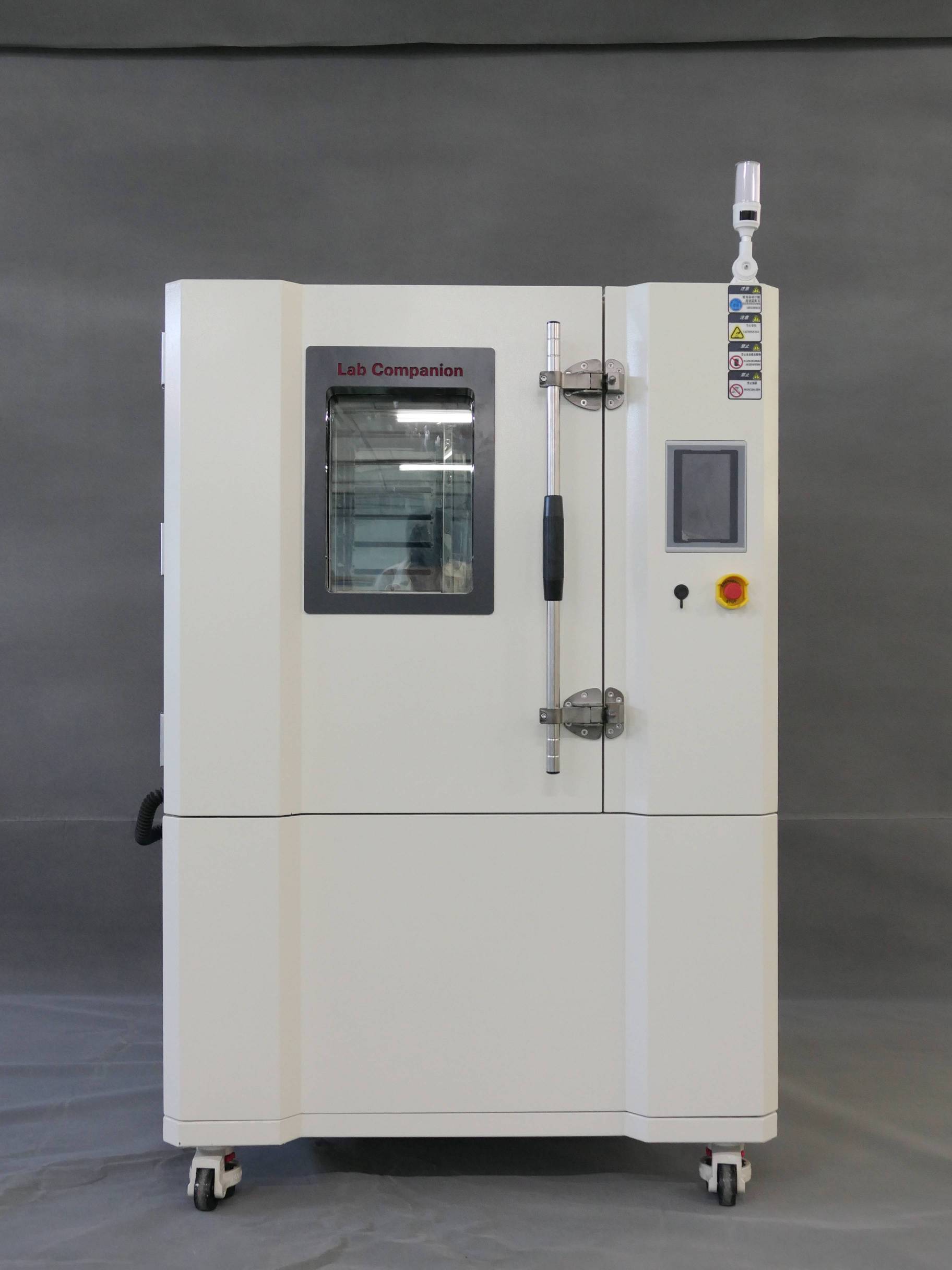
    In response to the testing and R&D requirements of electronic components such as semiconductors and automotive electronics, Lab Companion has developed a smaller capacity small rapid temperature change (wet heat) test chamber. While maintaining the advantages of standard rapid temperature change test chambers, it can also meet the needs of customers who have requirements for space size, with a single-phase 220VAC voltage specification. It can also meet the equipment usage requirements of customers in civilian office areas such as research institutions and universities. Its main features are as follows: 1. It has powerful heating and cooling performance 2. Heating rate: 15℃/min; Cooling rate: 15℃/min 3. (Temperature range: -45℃ to +155℃) 4. Single-phase 220VAC, meeting the electricity demands of more customers 5. Single-phase 220VAC, suitable for industrial and civil power supply specifications, can meet the equipment power demands of customers in civil office areas such as research institutions and universities. 6. The body is small and exquisite, with a compact structure and easy to move 7. The miniaturized structure design of the test chamber can effectively save configuration space. 8. The inner tank volume is 100L, the width is 600mm, the depth is less than 1400mm, and the product volume is less than 1.1m ³. It is suitable for the vast majority of residential and commercial elevators in China (GB/T7025.1). 9. The standard universal wheels enable the product to move freely at the installation site. 10. Standard air-cooled specification is provided, facilitating the movement and installation of the product 11. At the same time, it saves customers the cost and space of configuring cooling towers. 12. A more ergonomic operation touch screen design 13. Through the multi-angle adjustment of the touch screen, it can meet the operation needs and provide the best field of vision for users of different heights, making it more convenient and comfortable. 14. Energy-saving cold output temperature and humidity control system, with dual PID and water vapor partial pressure control, features mature technology and extremely high precision. 15. Network control and data acquisition can be carried out through the interface (RS-485/GPIB/Web Lan/RS-232C). 16. It is standard-equipped with left and right cable holes (50mm), which facilitates the connection of power on the sample and the conduct of multiple measurements. 17. The controller adopts a color LCD touch screen, which is simple and convenient to operate 18. Through the controller, two control methods, fixed value and program, can be selected to adapt to different applications. 19. The program control can be set to 100 modes, with 99 steps for each mode. Repeat the loop up to 999 times. 20. Multiple languages can be easily switched (Simplified Chinese, English), and test data can be stored on a USB flash drive.
    ЧИТАТЬ ДАЛЕЕ
  • Flame-retardant PP Materials in Industry Working Principle
    Oct 27, 2025
    Polypropylene (PP) itself is a highly flammable hydrocarbon with a limiting oxygen index (LOI) of only 17.8%. It will continue to burn even after being removed from the fire source. The core principle of flame-retardant PP is to interrupt or delay its combustion cycle through physical and chemical means. Combustion requires the simultaneous existence of three elements: combustible material, heat and oxygen. The function of flame retardants is to destroy this "burning triangle".   In industry, flame retardancy is mainly achieved by adding flame retardants to PP. Different types of flame retardants function through the following mechanisms: 1. Gas-phase flame retardant mechanism This is one of the most common mechanisms, especially applicable to traditional halogen-based flame retardants. When flame retardants are heated and decomposed, they can capture the free radicals (such as H· and HO·) that maintain the combustion chain reaction in the combustion reaction zone (flame), causing their concentrations to drop sharply and thus interrupting the combustion. 2. Condensed phase flame retardant mechanism This is the most mainstream mechanism of halogen-free flame-retardant PP. Flame retardants promote the formation of a uniform and dense carbon layer on the surface of polymers. This layer of carbon has three major functions. The first step is to prevent external heat from entering the interior of the polymer. Secondly, it prevents the escape of flammable gases inside and the entry of external oxygen. Finally, it inhibits the further pyrolysis of the polymer and the generation of smoke. When a fire occurs, the acid source promotes the dehydration, cross-linking and carbonization of the carbon source. Meanwhile, the large amount of gas produced by the decomposition of the gas source causes the softened carbon layer to expand, eventually forming a porous, dense and strong foam carbon layer, which protects the underlying PP like "armor". 3. Cooling/heat absorption mechanism Flame retardants absorb a large amount of heat during the decomposition process, reducing the surface temperature of polymers and making it difficult for them to continuously pyrolyze and produce flammable gases. Typical representatives include aluminium hydroxide (ATH) and magnesium hydroxide (MH). When they decompose, they absorb a large amount of heat (endothermic reaction) and release water vapor. The water vapor can not only dilute flammable gases but also play a cooling role. 4. Dilution mechanism Flame retardants decompose to produce a large amount of non-flammable gases (such as water vapor and CO₂, etc.), which can dilute the concentration of flammable gases and oxygen near the polymer surface, making combustion unsustainable. Both the gas sources of metal hydroxides and intumescent flame retardants have this function.   In conclusion, the working principle of flame-retardant PP in industry is a complex process involving the synergy of multiple mechanisms. Modern flame-retardant PP technology is developing towards halogen-free, low smoke, low toxicity and high efficiency. Among them, the condensed phase flame-retardant mechanism represented by intumescent flame retardants (IFR) is the core of current research and application. By carefully designing flame-retardant formulas, the best balance can be achieved among flame-retardant efficiency, material mechanical properties, processing performance and cost.
    ЧИТАТЬ ДАЛЕЕ
  • How is over-temperature protection carried out in a temperature test chamber?
    Oct 23, 2025
    The over-temperature protection of the temperature test chamber is a multi-level and multi-redundant safety system. Its core purpose is to prevent the temperature inside the chamber from rising out of control due to equipment failure, thereby protecting the safety of the test samples, the test chamber itself and the laboratory environment.   The protection system usually consists of the following key parts working together: 1. Sensor: The main sensor is used for the normal temperature control of the test chamber and provides feedback signals to the main controller. An independent over-temperature protection sensor is the key to a safety system. It is a temperature-sensing element independent of the main control temperature system (usually a platinum resistance or thermocouple), which is placed by strategically at the position within the box that best represents the risk of overheating (such as near the heater outlet or on the top of the working chamber). Its sole task is to monitor over-temperature. 2. Processing unit: The main controller receives signals from the main sensor and executes the set temperature program. The independent over-temperature protector, as an independent hardware device, is specifically designed to receive and process the signals from the over-temperature protection sensor. It does not rely on the main controller. Even if the main controller crashes or experiences a serious malfunction, it can still operate normally. 3. Actuator: The main controller controls the on and off of the heater and the cooler. The safety relay/solid-state relay receives the signal sent by the over-temperature protector and directly cuts off the power supply circuit of the heater. This is the final execution action.   The over-temperature protection of the temperature test chamber is a multi-level, hard-wire connected safety system designed based on the concepts of "redundancy" and "independence". It does not rely on the main control system. Through independent sensors and controllers, when a dangerous temperature is detected, it directly and forcibly cuts off the heating energy and notifies the user through sound and light alarms, thus forming a complete and reliable safety closed loop.
    ЧИТАТЬ ДАЛЕЕ
  • Принцип выравнивания температуры внутри испытательной камеры с помощью воздушного клапана
    Sep 22, 2025
    Его основной принцип – замкнутая система с отрицательной обратной связью «нагрев – измерение – управление». Проще говоря, она заключается в точном регулировании мощности нагревательных элементов внутри бокса для компенсации рассеивания тепла, вызванного внешней средой, тем самым поддерживая постоянную температуру испытания, превышающую температуру окружающей среды. Процесс стабилизации температуры воздушным клапаном представляет собой динамический и непрерывно регулируемый замкнутый контур: Сначала задайте заданную температуру. Датчик температуры измеряет фактическую температуру внутри контейнера в режиме реального времени и передаёт сигнал на ПИД-регулятор.Когда ПИД-регулятор вычисляет значение ошибки, он рассчитывает мощность нагрева, которую необходимо скорректировать, на основе значения ошибки с помощью ПИД-алгоритма. Алгоритм учитывает три фактора:P (пропорция): Какова величина текущей погрешности? Чем больше погрешность, тем больше диапазон регулировки мощности нагрева.I (интеграл): накопление ошибок за определённый период времени. Используется для устранения статических ошибок (например, если всегда присутствует небольшое отклонение, интегральный член постепенно увеличивает мощность до полного его устранения).D (дифференциал): скорость изменения текущей погрешности. Если температура быстро приближается к заданному значению, мощность нагрева будет заранее снижена, чтобы предотвратить «перерегулирование».3. ПИД-регулятор посылает рассчитанный сигнал на регулятор мощности нагревательного элемента (например, твердотельное реле SSR), который точно регулирует напряжение или ток, подаваемый на нагревательный провод, тем самым управляя его тепловыделением.4. Вентилятор непрерывно работает, обеспечивая быстрое и равномерное распределение тепла, генерируемого системой отопления. Кроме того, он оперативно передаёт изменения сигнала датчика температуры на контроллер, что обеспечивает более оперативную реакцию системы. Балансир воздушного клапана измеряет объём воздуха, при этом плотность воздуха меняется в зависимости от температуры. При одном и том же значении перепада давления массовый или объёмный расход воздуха, соответствующий разной плотности, различается. Поэтому температура должна быть стабилизирована на известном фиксированном значении, чтобы микропроцессор прибора мог точно рассчитать объём воздуха при стандартных условиях на основе измеренного значения перепада давления по заданной формуле. Нестабильная температура может привести к ненадёжным результатам измерений.
    ЧИТАТЬ ДАЛЕЕ
  • Принцип работы механического компрессионного холодильного агрегата с воздушным охлаждением Lab Companion Принцип работы механического компрессионного холодильного агрегата с воздушным охлаждением Lab Companion
    Sep 06, 2025
    1.СжатиеГазообразный хладагент, имеющий низкую температуру и низкое давление, выходит из испарителя и всасывается компрессором. Компрессор, потребляя электроэнергию, совершает работу над этой частью газа, интенсивно сжимая его. Когда хладагент превращается в перегретый пар с высокой температурой и высоким давлением, температура пара значительно превышает температуру окружающей среды, что создаёт условия для отвода тепла наружу.2. КонденсацияПары хладагента, находящиеся под высоким давлением и температурой, поступают в конденсатор (обычно это ребристый трубчатый теплообменник, состоящий из медных трубок и алюминиевых ребер). Вентилятор обдувает ребра конденсатора потоком окружающего воздуха. Затем пары хладагента отдают тепло проходящему через конденсатор воздуху. Охлаждаясь, они постепенно конденсируются из газообразного состояния в жидкость средней температуры и высокого давления. При этом тепло от холодильной системы передается в окружающую среду.3. РасширениеЖидкий хладагент средней температуры и высокого давления протекает по узкому каналу через дроссельное устройство, которое служит для дросселирования и снижения давления, подобно тому, как если бы вы перекрывали пальцем отверстие водопроводной трубы. При резком падении давления хладагента резко падает и его температура, превращаясь в низкотемпературную и низконапорную двухфазную газожидкостную смесь (туман).4. ИспарениеГазожидкостная смесь низкого давления и температуры поступает в испаритель, а другой вентилятор обеспечивает циркуляцию воздуха внутри камеры через холодные ребра испарителя. Жидкий хладагент поглощает тепло воздуха, проходящего через ребра испарителя, быстро испаряется и превращается в газ с низкой температурой и давлением. Благодаря поглощению тепла температура воздуха, проходящего через испаритель, значительно снижается, что обеспечивает охлаждение испытательной камеры. Затем этот газ с низкой температурой и низким давлением снова всасывается в компрессор, запуская следующий цикл. Таким образом, цикл повторяется бесконечно. Холодильная система непрерывно «переносит» тепло из контейнера наружу и рассеивает его в атмосферу с помощью вентилятора.
    ЧИТАТЬ ДАЛЕЕ

оставить сообщение

оставить сообщение
Если вы заинтересованы в нашей продукции и хотите узнать более подробную информацию, пожалуйста, оставьте сообщение здесь, мы ответим вам, как только сможем.
представлять на рассмотрение

Дом

Продукты

WhatsApp

связаться с нами